Hey all -- I am fighting a high CHT issue on my O235 and am curious how much of a spread in CHT temps you guys normally see in cruise or climb.
It would be interesting if you note how you measured the temps, if you are injected or carbed, and if you are running standard ignition timing on <whatever> engine as well.
CHT spreads?
Wed Oct 15, 2014 3:07 pm
- motosix offline
- Posts: 238
- Joined: Sat Oct 05, 2013 4:37 pm
- Location: Denver
- FindMeSpot URL: http://tinyurl.com/redcubby
Wed Oct 15, 2014 5:36 pm
Re: CHT spreads?
You can't really judge much without also specifying the aircraft type, ie: The configuration of the cowling.
In Husky and Super Cub type airplanes with four probe EGT/CHT, I've regularly seen the number three cylinder run on the order of 50 to 70 degrees warmer than others.
In my Cessna 170 with AvCon conversion O-360 Lycoming, number 2 cylinder ran much warmer than all the others, again, 50 to 70 degrees warmer.
All this information was derived using calibrated electronic sensors, and I believe these numbers to be accurate.
MTV

Wed Oct 15, 2014 6:59 pm
Re: CHT spreads?
Mine's an O-360 Lycoming A1A /Avcon conversion in my P172D. It has cowl flaps. The back two cylinders typically run about 30-50 degrees warmer than the front cylinders. The difference between the front two is rarely more than 10 degrees, and similarly the back ones run within 10-15 degrees of each other. The engine is carbureted. I have an Insight G1 analyzer. On climb out, I can count on the back two cylinders getting above 420F, cooling down below that after leveling off and setting cruise power. In hot weather, I have to run with the cowl flaps partly open at cruise.
I was having a lot of serious overheat problems for awhile, with the back two occasionally hitting 460F. I took the time to clean between the fins of the cylinders, and my IA made new baffle strips for the baffles. Things improved marginally, but not enough. Upon the suggestion of Mike Busch, who is known to most as an engine guru, my IA reduced the timing 10 degrees from 20 BTC which Lycoming calls for to 10 BTC. Mike advised that other models of O-360s have been authorized by Lycoming to run 10 BTC but for some reason the A1A was omitted. My IA was reluctant, because he thought it would cause a power loss, but he did it anyway. That made a big difference and resulted in what I described above, and I can't tell that there has been any power loss at all. I've been running it that way for about 1 1/2 years now.
Cary

"I have slipped the surly bonds of earth..., put out my hand and touched the face of God." J.G. Magee
Wed Oct 15, 2014 7:09 pm
Re: CHT spreads?
Perfect, thanks!
My application is a carb'd O235 in an experimental Wag Aero Cubby (J3 look alike) with a whole 60 hours on the motor. My #4 is the problem child, and it just so happens to be the cylinder the rear-mounted oil cooler is sucking air off of. My #3 is one of the coolest strangely enough.
I blocked the oil cooler off all together (temporarily to test) in an attempt to prove the baffles are OK, but while all other cylinders will cruise at 330-350, #4 will climb to 410+ and stay there at cruise no matter how rich I make it. On climb #2 and #4 are the hottest, but 1/2/3 cool off quickly once leveling off. My measurements are made from the lower CHT bayonet plug directly into the cylinder head (not under the plug) and up to a Dynon 180 dash, and the probes are all checking out electrically. That all said, I am seeing 40-60 degree spread from 1/2/3 to #4 and was curious how common this is.
I am going to shit can the existing baffles and get the oil cooler off the back of #4 as one last attempt to solve the issue before pulling the cylinder to look for glazing...
- motosix offline
- Posts: 238
- Joined: Sat Oct 05, 2013 4:37 pm
- Location: Denver
- FindMeSpot URL: http://tinyurl.com/redcubby
Wed Oct 15, 2014 7:17 pm
Re: CHT spreads?
...interesting note about the timing Cary, and that is why I asked for that detail.
I found my 235 to be timed for 25BTDC where the engine plate calls for 20. The older Lycomings were all 25 I gather with the newer (and higher compression) ones calling for 20. At our altitude we should be able to run +5 timing on avgas without any huge detonation fears (experimentals mind you), but that is why I included it in my initial question. Possibly my number 4 really really really hates 25 degrees and would straighten up and fly right at 20. I'll find out once I reconfigure the baffling a bit.
I found my 235 to be timed for 25BTDC where the engine plate calls for 20. The older Lycomings were all 25 I gather with the newer (and higher compression) ones calling for 20. At our altitude we should be able to run +5 timing on avgas without any huge detonation fears (experimentals mind you), but that is why I included it in my initial question. Possibly my number 4 really really really hates 25 degrees and would straighten up and fly right at 20. I'll find out once I reconfigure the baffling a bit.
- motosix offline
- Posts: 238
- Joined: Sat Oct 05, 2013 4:37 pm
- Location: Denver
- FindMeSpot URL: http://tinyurl.com/redcubby
Wed Oct 15, 2014 11:47 pm
Re: CHT spreads?
20-50. IO520 A185F
- NineThreeKilo offline
- Retired
- Posts: 1679
- Joined: Thu Dec 31, 2009 8:16 pm
- Location: _
Thu Oct 16, 2014 6:23 am
Re: CHT spreads?
motosix wrote:Perfect, thanks!
My application is a carb'd O235 in an experimental Wag Aero Cubby (J3 look alike) with a whole 60 hours on the motor. My #4 is the problem child, and it just so happens to be the cylinder the rear-mounted oil cooler is sucking air off of. My #3 is one of the coolest strangely enough.
I blocked the oil cooler off all together (temporarily to test) in an attempt to prove the baffles are OK, but while all other cylinders will cruise at 330-350, #4 will climb to 410+ and stay there at cruise no matter how rich I make it. On climb #2 and #4 are the hottest, but 1/2/3 cool off quickly once leveling off. My measurements are made from the lower CHT bayonet plug directly into the cylinder head (not under the plug) and up to a Dynon 180 dash, and the probes are all checking out electrically. That all said, I am seeing 40-60 degree spread from 1/2/3 to #4 and was curious how common this is.
I am going to shit can the existing baffles and get the oil cooler off the back of #4 as one last attempt to solve the issue before pulling the cylinder to look for glazing...
That really doesn't sound bad for a four cylinder Lyc...... The other question is what OATs were these CHTs noted in? High temps or cool?
The oil cooler will rob some air off one cylinder, if mounted aft, but that's common in certificated a/c and it works.
Have you verified the condition and security of your inter cylinder baffles, as well as your main baffles? I recently found an intern cylinder baffle hanging below the engine during pre flight. I don't have four point CHT on this plane, so I don't know what that did to CHT on aft cylinder, but I'm sure it had an effect.
MTV
Thu Oct 16, 2014 8:06 am
Re: CHT spreads?
motosix wrote:......., but while all other cylinders will cruise at 330-350, #4 will climb to 410+ and stay there at cruise no matter how rich I make it. On climb #2 and #4 are the hottest, but 1/2/3 cool off quickly once leveling off. .....
While it'd be nice to have all the CHT's close, it might not be possible with the way the engine is baffled esp with a non-injected engine. I checked the TCDS (#E-233) and it looks like using a well-type thermocouple the CHT redline is 500 degrees. Your 410 reading is well below that. Don't know what model O-235 you have, but I see that the timing for most is spec'd at 25 degrees BTDC, a couple are spec'd at 20 and one (C1A) is 15 degrees.
My small Continentals have been in the 26-28 degree range, my 320 is 25/25, and my new O-470K is 22. I'm no engineer and I have to admit that I don't get this-- it seems weird that the basic opposed-type air-cooled aircraft engine design would vary so much on the timing.

Cessna Skywagon -- accept no substitute!
Mon Nov 03, 2014 10:33 am
Re: CHT spreads?
I wanted to post an update for anyone in the future who runs into a similar problem. To re-cap, my CHTs in my Wag Aero J3(ish) clone were 415-420 in cruise on cylinder 4 with cyls 1-3 around 340ish at 70F OAT. The cylinder temp was below "red line", but anything over 400 degrees is too much for any extended life of that cylinder in my humble opinion...
After a bunch of testing and fabrication (and re-fabrication), I am happy to report my CHTs are now all within 5-10 degrees of each other and ~330 deg F in cruise at 65ish OAT @ 7000MSL. I am happy to go into details for anyone interested, but the biggest factor was a redesign of the cylinder 4 baffle to allow more air mass between the cylinder cooling fins and the back wall where the oil cooler is mounted. Size, shape, and location of cooling holes in the rear baffle (to cool oil cooler) also made a measurable difference, as well as running the O235 at 20 degrees BTDC instead of 25. If I spend a few more days re-doing some other questionable baffle work I am sure I can pick up a few more degrees, but overall I am extremely pleased that I can now finally get out of the pattern and enjoy the new bird.
After a bunch of testing and fabrication (and re-fabrication), I am happy to report my CHTs are now all within 5-10 degrees of each other and ~330 deg F in cruise at 65ish OAT @ 7000MSL. I am happy to go into details for anyone interested, but the biggest factor was a redesign of the cylinder 4 baffle to allow more air mass between the cylinder cooling fins and the back wall where the oil cooler is mounted. Size, shape, and location of cooling holes in the rear baffle (to cool oil cooler) also made a measurable difference, as well as running the O235 at 20 degrees BTDC instead of 25. If I spend a few more days re-doing some other questionable baffle work I am sure I can pick up a few more degrees, but overall I am extremely pleased that I can now finally get out of the pattern and enjoy the new bird.
- motosix offline
- Posts: 238
- Joined: Sat Oct 05, 2013 4:37 pm
- Location: Denver
- FindMeSpot URL: http://tinyurl.com/redcubby
Mon Nov 03, 2014 12:09 pm
Re: CHT spreads?
Do you have and photos of what you did? I'm probably not alone in wanting to see.
- amacbean offline

- Posts: 544
- Joined: Mon Aug 08, 2005 3:22 pm
- Location: Springville
- FindMeSpot URL: http://share.findmespot.com/shared/face ... 7GsCKYBvNX
- Aircraft: Cessna 170b
Mon Nov 03, 2014 1:00 pm
Re: CHT spreads?
amacbean wrote:Do you have and photos of what you did? I'm probably not alone in wanting to see.
I will take some the next time I am up at my hangar as long as my novice sheet metal skills are not mocked too bad.
The "before" looked like this:

The cylinder 4 fins are right on next to the wall of the rear baffle, and this appears common on some cub-variants and almost all of the RVs. The oil cooler on mine was rather hastily mounted on the rear of the baffle by the original builder. The large-ish square hole was machined out of the baffle is far too large for both cooling needs as well as pressure gradient purposes. You can see the fins of the oil cooler directly above the number 4 top spark plug wire. There are a variety of different indications this was an on-going problem for this cylinder and that the builder attempted a variety of fixes (like I did).
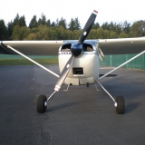
This is not mine but similar in construction and you can see how most installs put the oil cooler directly next to the cylinder like this:
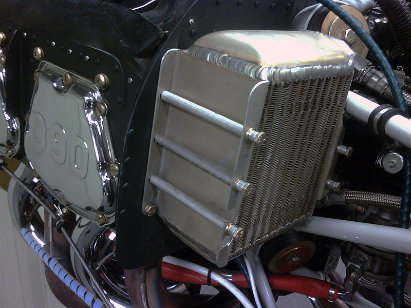
Here was mine before:

My theory was that since my plane is so slow there was little ram-air effect to aid in cooling on that rear cylinder even with a air-ramp in front of the front two cylinders. I already have cowl flaps and they were fabricated wide-open, so without being able to create more vacuum I believed I needed a bit more air mass to keep the oil cooler and #4 cylinder from heat soaking each other while slowing down the air movement across the oil cooler. This was my theory at least and there is a bit of anecdotal information on the Cub forums supporting it indirectly...
The current working solution was to build a box around the cylinder head portion and provide an inch of air gap between the cylinder and rear baffle, and then wrap that box all the way down to the bottom of the cylinder to allow that air mass to reach around and under before terminating in the normal bends (aluminum fingers) that reach around under the cylinders and are secured by through-bolts.
The oil cooler still mounts on the back of the baffle (with much more bracketing to support the weight of it), but it is not right on top of the cooling fins and does not have direct air flow via large holes. My oil temps were sub-150 degree at first and were way too cold with direct air flow. With the old baffling and the oil cooler completely covered up the CHTs did not improve and my oil temps were ~200 degrees F @ ~70 deg OAT.
I tried various sized air-openings through the baffle to the oil cooler by making different aluminum inserts then quickly swapping them out after a trip around the pattern. I stumbled across a simple perforation idea which works the best for my particular setup. I machined 30 or so 1/8" holes to retain the pressure and limit the air flow out of the baffle to the oil cooler and tested the number by covering up different amounts with tape. For the current temps, 10 holes is about right. Having the holes at the bottom of the box versus the top makes a slight difference as well (warmer oil temps for the same CHT temp) and "less holes with a larger diameter" does not seem to work as well as "more holes with a smaller diameter" (which is something I did not expect).
My current plan is to offset the oil cooler mount slightly more and fab up a small aluminum plate that slides back and forth to allow me to quickly adjust the air flow to the oil cooler but remains rigid once "set" in position. For the mean time I am happy simply covering up a few holes with tape and finally getting to fly the little project!
I'll try and take some decent pictures the next chance I get.
- motosix offline
- Posts: 238
- Joined: Sat Oct 05, 2013 4:37 pm
- Location: Denver
- FindMeSpot URL: http://tinyurl.com/redcubby
Tue Nov 04, 2014 9:07 am
Re: CHT spreads?
It just dawned on me that you might have bought the red Cubby that was for sale at Independence Oregon. A friend of mine lives there and when I was (briefly) thinking about buying a Cub last summer, I flew down and took a look at it. Seemed like a good airplane, a couple things I didn't care for but overall pretty darn nice and all brand new. The owner (follow-on & buddy to the original builder) and another guy (the test pilot) had been scratching their heads over high CHT's, I guess they didn't get that resolved but apparently you have. Good show. And congrats on your new airplane. It looked like it'd be a real hoot to fly.
Cessna Skywagon -- accept no substitute!
Tue Nov 04, 2014 9:55 am
Re: CHT spreads?
hotrod180 wrote:It just dawned on me that you might have bought the red Cubby that was for sale at Independence Oregon. A friend of mine lives there and when I was (briefly) thinking about buying a Cub last summer, I flew down and took a look at it. Seemed like a good airplane, a couple things I didn't care for but overall pretty darn nice and all brand new. The owner (follow-on & buddy to the original builder) and another guy (the test pilot) had been scratching their heads over high CHT's, I guess they didn't get that resolved but apparently you have. Good show. And congrats on your new airplane. It looked like it'd be a real hoot to fly.
Thats the one. There definitely were/are a few squawks here and there but overall it is a ball to fly; very, very slowly.
The CHT issued confused most all of the A&Ps on my field too since the original install was so commonplace. I had nothing to lose by trying out some ideas though and am happy I got lucky and stumbled across a working solution. They don't call them "experimental" for nothing!
- motosix offline
- Posts: 238
- Joined: Sat Oct 05, 2013 4:37 pm
- Location: Denver
- FindMeSpot URL: http://tinyurl.com/redcubby
Sun Oct 07, 2018 4:29 pm
Re: CHT spreads?
PPonked 1976 180J
Bob
Bob
Mon Oct 08, 2018 6:23 am
Re: CHT spreads?
Cary wrote:Mine's an O-360 Lycoming A1A /Avcon conversion in my P172D. It has cowl flaps. The back two cylinders typically run about 30-50 degrees warmer than the front cylinders. The difference between the front two is rarely more than 10 degrees, and similarly the back ones run within 10-15 degrees of each other. The engine is carbureted. I have an Insight G1 analyzer. On climb out, I can count on the back two cylinders getting above 420F, cooling down below that after leveling off and setting cruise power. In hot weather, I have to run with the cowl flaps partly open at cruise.
I was having a lot of serious overheat problems for awhile, with the back two occasionally hitting 460F. I took the time to clean between the fins of the cylinders, and my IA made new baffle strips for the baffles. Things improved marginally, but not enough. Upon the suggestion of Mike Busch, who is known to most as an engine guru, my IA reduced the timing 10 degrees from 20 BTC which Lycoming calls for to 10 BTC. Mike advised that other models of O-360s have been authorized by Lycoming to run 10 BTC but for some reason the A1A was omitted. My IA was reluctant, because he thought it would cause a power loss, but he did it anyway. That made a big difference and resulted in what I described above, and I can't tell that there has been any power loss at all. I've been running it that way for about 1 1/2 years now.
Cary
This is interesting, I have a very similar setup, (C175, O-360-A1A although no cowl flaps) and at cruise (2450RPM), I am seeing all my CHT's within 10 deg and depending on OAT, somewhere between 295-330 F. On climbout, even leaving full power on for a long climb I don't see CHT's go much above 350. I think I might have seen 370 once. I'm running 25deg. BTDC.
DISPLAY OPTIONS
Who is online
Users browsing this forum: No registered users and 3 guests
Latest Features
-
Live to Tell
A Minnesota pilot is surprised to learn that the sudden asymmetric drag of an out-of-rig ski can…Read More -
Creators
Working in some of the Yukon's most beautiful and remote environments, photographer Simon Blakesley captures aircraft in…Read More -
Aircraft Ownership and Maintenance
Upgrading to big tires can make a huge difference in backcountry performance, but with those gains come…Read More -
Tales from Yesteryear
In this tale from bush flying yesteryear, Don Cogger signs up to help Atlee Dodge Jr recovery…Read More


Latest Knowledge Base
-
Destinations
A regional guide with ideas for winter camping destinations in California, Nevada, New Mexico, and Arizona.Read More -
Aircraft
Finding an affordable aircraft that can handle the backcountry for $80K or less? A challenge for sure, but with the…Read More -
Aircraft
01.29.2018 - Zane - Updated tire diameter graphic to add 8.50x10 Guide to tires for use in the backcountry and off-airport landing…Read More -
Pilots
12.22.2013 - Initial article format Operating aircraft on skis and negotiating a snow-covered landscape is an entirely unique skillset and environment.…Read More


